Thursday, May 15, 2014

Week 6: (Outside-Lab) Adjustable Wheels and Testing

This week, our team worked on trying to make the wheels adjustable according to the individual's height. After working within the Machine Shop, modifications such as the addition of Gorilla Tape and polishing the rods were made. This helped to keep the rods in place while the pin was pressed to allow a 4" range of heights for the legs. The tape prevented the rod from moving around while the walker was in motion.

Another objective of this week was to create the testing that would be done to test the walker. The first type included weight testing, in order to ensure the walker could support the body weight of varying sizes. In this test, a board was placed overtop of the frame in the desired position and barbell weights were placed on either side, representing the individual's weight that would be distributed on each side. This was done to simulate someone getting into the walker from a seated position. As a result, the walker is capable of accommodating a 350 pound load on the back and front of the side frames, where the weight would be distributed while walking or getting up from a seated position.  This also concluded the frame would not tilt while someone was trying to get up from a seated position, due to the 10 degree angle of the front legs.

Next, the coefficient of static friction was tested to determine the overall traction of the wheels of the walker. In order to perform this test, the walker was placed on two boards on the ground, with the wheels remaining in a locked position. As the top board was lifted from one side, the angle at which the walker began to move was used to create a free body diagram. This tangent of the angle helped to determine the coefficient of static friction.

Finally, the effectiveness of the walker to reduce Lumbar Degenerative Kyphosis, poor posture
resulting from osteoporosis and disk displacement, was tested. Our team created a mannequin out of wood, leftover piping and bolts to test with. The arms of this individual and the lower back region would bend, simulating the spine bending. With this, the angle of the spine was measured from a vertical position and recorded to test if a significant amount of improvement occurred between this walker design and current walkers available on the market.


Week 7: (Outside-Lab) Braking Line System Adjustments

After meeting in the Machine Shop, our team realized we needed to have more brake line available for the walker's brakes.

The brake handles that were assembled in lab, were attached to a short black braking wire that would be attached to the stoppers placed on top of the wheels. This stopper currently rests on the rubber coated wheels, preventing the walker from moving forward involuntarily. Our team is creating a reverse process of the original braking system, in that the brake will always be engaged unless the lever is pulled. The braking line will be attached to the stopper so that when the handle is gripped on the armrests, the stopper will be released onto the wheel, creating the braking motion. The stopper will be positioned upward, off of the wheel, until the user presses the handle inward.

In this situation, an old bike's brake line was detached to be wrapped around the stopper. As seen in Figure 1, one teammate attempts to disassemble the brake line from the bike. This was done using a wrench and screw driver, untwisting the line from the brakes. This extra wire will be useful for the attachment of the brakes.
Figure 1: This image displays one teammate disassembling the brake line from the old bike.

Until the walker is retrieved from the Machine Shop, our team will be creating the foam padding for the armrests. More updates are soon to follow this progress.

Week 7: (In-Lab) Construction and Brake Line System

After a rigorous meeting in the Drexel Machine Shop, slight modifications were made to the physical structure of the frame of the walker.

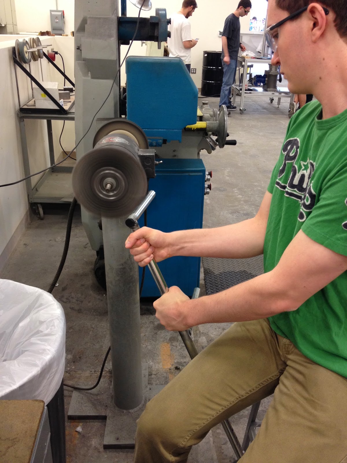
Due to the angled legs on the front of the walker, the initial measurements of the arm rests made it difficult to close into an easily stored, compacted device. A 5" long measurement of piping was made in the middle of each side and removed with a hacksaw initially, and then assisted with a bandsaw. These pieces of siding, as seen in Figure 1, would then be welded together to reconstruct the frame. Prior to welding these pieces, the exposed ends in the middle had to be sanded in order to remove the coating that covers the steel piping. One team member, in Figure 2, held the frame while the ends were being sanded, creating an easier spot for the welding to adhere and occur.
Figure 1: This image displays the cut and disassembled frame, waiting to be welded together. 
Figure 2: This image shows one team member sanding the ends of the unpolished frame. 

Next, the thinner sized piping was measured and fitted with two metal T-Plates, one on each end. While holding the T-Plate against the piping, two holes were measured and clamped onto the work bench. The holes were drilled and the T-Plate was riveted onto the piping. This piece would be attached to the walker shortly after the welding has been completed.

Another major detail that was addressed was the braking line system that would be attached to the front of the armrests. The handles with the attached brake line were disassembled previously and modified within the Machine Shop. First, the metal piping attached to the handle was measured and cut with bandsaw, to fit the thinner piping inside of. The idea was to flip the handle around so that it could be gripped from easily from resting position. After fitting the piping within the handle grips, two holes were drilled through the piping. These were then riveted to securely attach the new piping to the handle grips, as seen in Figure 3. The black wire hanging from the handle is the braking system that will be attached to the stopper at the bottom of the legs.
 Figure 3: This picture displays one team member drilling two holes through the piping and handle. 

After these adjustments were made, the disassembled frame was left with the Machine Shop to be welded together at the polished edges. The next step the team would like to accomplish is attaching the braking system to the walker, allowing the gripped handles to stop the walker from moving forward.