Due to the angled legs on the front of the walker, the initial measurements of the arm rests made it difficult to close into an easily stored, compacted device. A 5" long measurement of piping was made in the middle of each side and removed with a hacksaw initially, and then assisted with a bandsaw. These pieces of siding, as seen in Figure 1, would then be welded together to reconstruct the frame. Prior to welding these pieces, the exposed ends in the middle had to be sanded in order to remove the coating that covers the steel piping. One team member, in Figure 2, held the frame while the ends were being sanded, creating an easier spot for the welding to adhere and occur.

Figure 1: This image displays the cut and disassembled frame, waiting to be welded together.
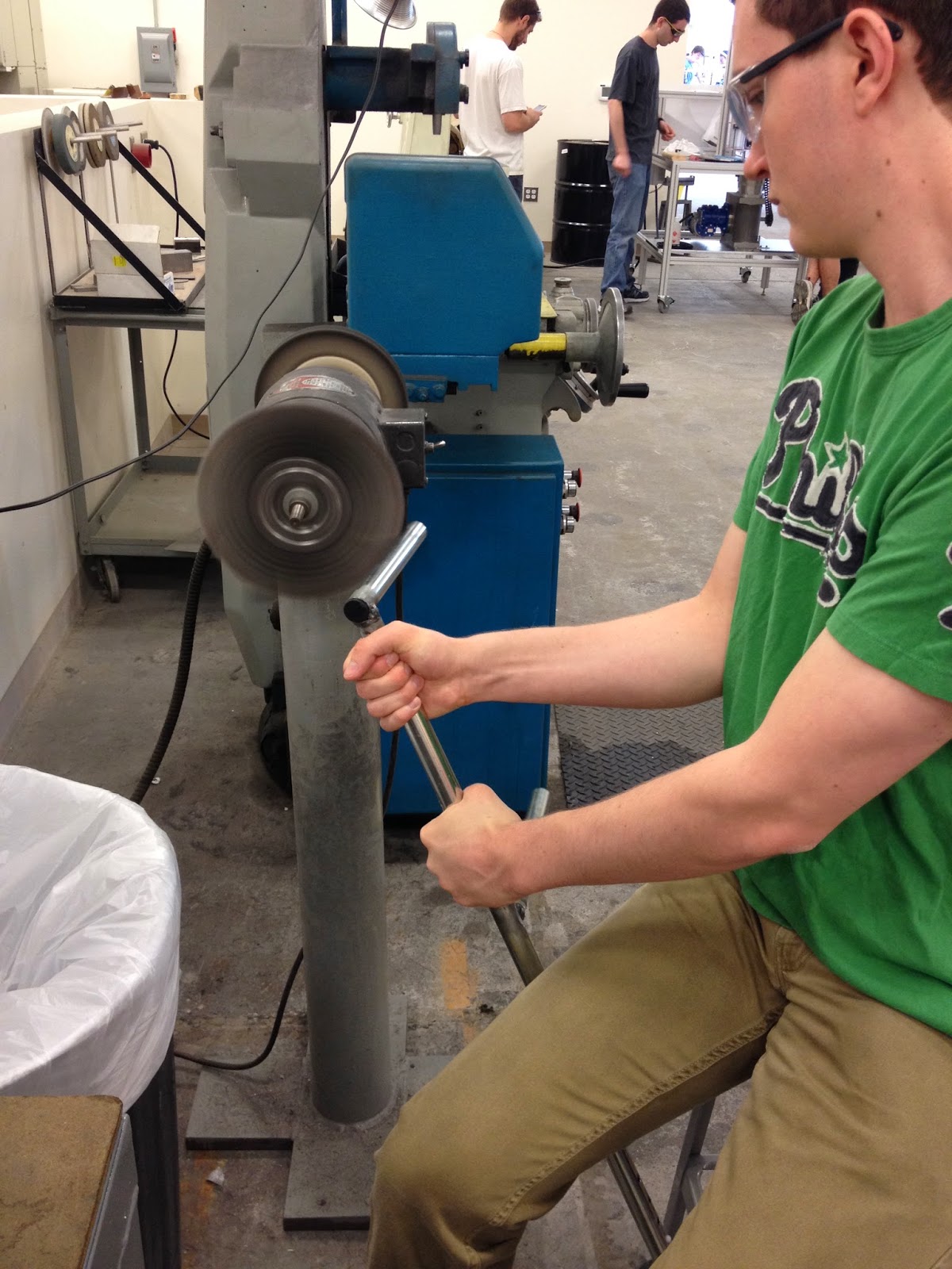
Figure 2: This image shows one team member sanding the ends of the unpolished frame.
Another major detail that was addressed was the braking line system that would be attached to the front of the armrests. The handles with the attached brake line were disassembled previously and modified within the Machine Shop. First, the metal piping attached to the handle was measured and cut with bandsaw, to fit the thinner piping inside of. The idea was to flip the handle around so that it could be gripped from easily from resting position. After fitting the piping within the handle grips, two holes were drilled through the piping. These were then riveted to securely attach the new piping to the handle grips, as seen in Figure 3. The black wire hanging from the handle is the braking system that will be attached to the stopper at the bottom of the legs.

Figure 3: This picture displays one team member drilling two holes through the piping and handle.
After these adjustments were made, the disassembled frame was left with the Machine Shop to be welded together at the polished edges. The next step the team would like to accomplish is attaching the braking system to the walker, allowing the gripped handles to stop the walker from moving forward.
No comments:
Post a Comment