This week, our team finished up some of the final touches on the walker. After each hook was attached to the side frames for the braking system, the team decided to "jazz" up the look of the finished product. With the presentation in mind, the team chose to paint the walker a dark blue color to give it an overall polished finish. Although the foam padding on the arm rests weren't added like planned, the prototype successfully achieved our initial problem statements.
This design was targeted towards the elderly community, therefore the dark blue gives it a more appealing and upbeat look when compared to the conventional silver walkers on the market. Although this is just a prototype, our team would hope to appeal to different targeted audiences besides the chosen elderly community.
Overall, our team is really impressed with the way our final product came out. Not only did this follow our initial design, but exceeded our highest expectations.
Aside from finishing the walker, the team continued to work on the presentation and deliverables required for this product.
Monday, June 2, 2014
Wednesday, May 28, 2014
Week 9: (In-Lab) Presentation
After multiple attempts of bending the hooks for the brake line system, the team could successfully complete this part of construction of the walker. The remaining tasks include painting the walker and attaching the foam padding to the back and arm rests.
For the remaining portion of the lab, the team worked on brainstorming how the presentation would be completed for the following week. A google powerpoint was created so that each team member could individually work on slides to illustrate the design process of the walker. The team decided which slides would be given to each member while discussing the best way to present our project. The next step would be to create the poster displaying the walker and the sales pitch that our group will be giving to the class.
For the remaining portion of the lab, the team worked on brainstorming how the presentation would be completed for the following week. A google powerpoint was created so that each team member could individually work on slides to illustrate the design process of the walker. The team decided which slides would be given to each member while discussing the best way to present our project. The next step would be to create the poster displaying the walker and the sales pitch that our group will be giving to the class.
Week 8: (Outside-Lab) Attaching Hooks and Angle Testing
After the necessary measurements were made on each leg, the hooks were attached to the walker. This would aid in holding the brake line at various heights. As seen in Figure 1, the small circular hooks were attached along the inner bar on both side frames. Each hook had to be opened to allow the brake line to comfortably sit while creating tension when the brake handle is manually pulled. Unfortunately this task was quite difficult because the hooks continually broke as one team member attempted to pry the circle open. Needless to say, the team went through plenty of these hooks until the desired number of hooks were achieved. As each height of the leg is adjusted, as seen in Figure 2, the brake line can be moved to the tightest position to allow for accurate braking.


Figure 1: This picture displays the circular hooks that were used for the brake line.
Figure 2: This picture displays the four hooks that were attached for each adjusted height of the legs.
Also, the team further tested the proper angle that the back rest would be adjusted to. This would allow for proper posture that the team's original goal was directed towards. To complete this task, as seen in Figure 3, two yard sticks were used to make makeshift metal arms that could bend at the shoulder, simulating an elderly using the walker.
Figure 3: This picture displays the yardsticks attached to the side frame to determine the angle of the back.
The bar going across the back of the walker, simulates the shoulders of the individual while the vertical bars attached with a bolt represented the elbows. This allowed the bars to freely move as if the individual were bending the elbows.
Figure 4: This picture displays a team member accurately measuring the angle of the yard stick.
After multiple angles were tested, the team determined a 20 degree angle, as seen in Figure 4, would be the most accurate and efficient angle for the walker. Many individuals that suffer from Kyphosis, an angle of 45 degrees, can reduce this effect with the adjusted degree of the back.
Tuesday, May 27, 2014
Week 8: (In-Lab) Braking System Adjustments
After the team met outside of lab to assess the braking system lines, the proper measurements were made for the wires that would connect to the stopper of the brakes. These ends were clipped and assembled to the modified stopper on the stationary back two wheels. As seen in Figure 1, one teammate makes the final measurements to attach the braking wire to the walker's side frames.

Figure 1: This photo displays one teammate measuring the braking line for the brakes.
First, each measurement was made by moving the cable after the legs were adjusted to the four various heights. Then, this cable will then be attached to a mechanism (hook) that allows the cable to rest in a desired notch. This will keep the braking cable tight and ready to be pulled via the braking handles.

Figure 2: This photo displays the front view of the walker as one teammate adjusts the back legs.
As seen in Figure 2, one teammate is adjusting the height of the legs while pushing in the pin to measure and mark the locations of where the hooks will attach to the brake line. The next step of this process will be to attach the hooks and connect the brake lines to them.
Thursday, May 15, 2014
Week 6: (Outside-Lab) Adjustable Wheels and Testing
This week, our team worked on trying to make the wheels adjustable according to the individual's height. After working within the Machine Shop, modifications such as the addition of Gorilla Tape and polishing the rods were made. This helped to keep the rods in place while the pin was pressed to allow a 4" range of heights for the legs. The tape prevented the rod from moving around while the walker was in motion.
Another objective of this week was to create the testing that would be done to test the walker. The first type included weight testing, in order to ensure the walker could support the body weight of varying sizes. In this test, a board was placed overtop of the frame in the desired position and barbell weights were placed on either side, representing the individual's weight that would be distributed on each side. This was done to simulate someone getting into the walker from a seated position. As a result, the walker is capable of accommodating a 350 pound load on the back and front of the side frames, where the weight would be distributed while walking or getting up from a seated position. This also concluded the frame would not tilt while someone was trying to get up from a seated position, due to the 10 degree angle of the front legs.
Next, the coefficient of static friction was tested to determine the overall traction of the wheels of the walker. In order to perform this test, the walker was placed on two boards on the ground, with the wheels remaining in a locked position. As the top board was lifted from one side, the angle at which the walker began to move was used to create a free body diagram. This tangent of the angle helped to determine the coefficient of static friction.
Finally, the effectiveness of the walker to reduce Lumbar Degenerative Kyphosis, poor posture
resulting from osteoporosis and disk displacement, was tested. Our team created a mannequin out of wood, leftover piping and bolts to test with. The arms of this individual and the lower back region would bend, simulating the spine bending. With this, the angle of the spine was measured from a vertical position and recorded to test if a significant amount of improvement occurred between this walker design and current walkers available on the market.
Week 7: (Outside-Lab) Braking Line System Adjustments
After meeting in the Machine Shop, our team realized we needed to have more brake line available for the walker's brakes.
The brake handles that were assembled in lab, were attached to a short black braking wire that would be attached to the stoppers placed on top of the wheels. This stopper currently rests on the rubber coated wheels, preventing the walker from moving forward involuntarily. Our team is creating a reverse process of the original braking system, in that the brake will always be engaged unless the lever is pulled. The braking line will be attached to the stopper so that when the handle is gripped on the armrests, the stopper will be released onto the wheel, creating the braking motion. The stopper will be positioned upward, off of the wheel, until the user presses the handle inward.
In this situation, an old bike's brake line was detached to be wrapped around the stopper. As seen in Figure 1, one teammate attempts to disassemble the brake line from the bike. This was done using a wrench and screw driver, untwisting the line from the brakes. This extra wire will be useful for the attachment of the brakes.

Until the walker is retrieved from the Machine Shop, our team will be creating the foam padding for the armrests. More updates are soon to follow this progress.
The brake handles that were assembled in lab, were attached to a short black braking wire that would be attached to the stoppers placed on top of the wheels. This stopper currently rests on the rubber coated wheels, preventing the walker from moving forward involuntarily. Our team is creating a reverse process of the original braking system, in that the brake will always be engaged unless the lever is pulled. The braking line will be attached to the stopper so that when the handle is gripped on the armrests, the stopper will be released onto the wheel, creating the braking motion. The stopper will be positioned upward, off of the wheel, until the user presses the handle inward.
In this situation, an old bike's brake line was detached to be wrapped around the stopper. As seen in Figure 1, one teammate attempts to disassemble the brake line from the bike. This was done using a wrench and screw driver, untwisting the line from the brakes. This extra wire will be useful for the attachment of the brakes.
Figure 1: This image displays one teammate disassembling the brake line from the old bike.
Until the walker is retrieved from the Machine Shop, our team will be creating the foam padding for the armrests. More updates are soon to follow this progress.
Week 7: (In-Lab) Construction and Brake Line System
After a rigorous meeting in the Drexel Machine Shop, slight modifications were made to the physical structure of the frame of the walker.
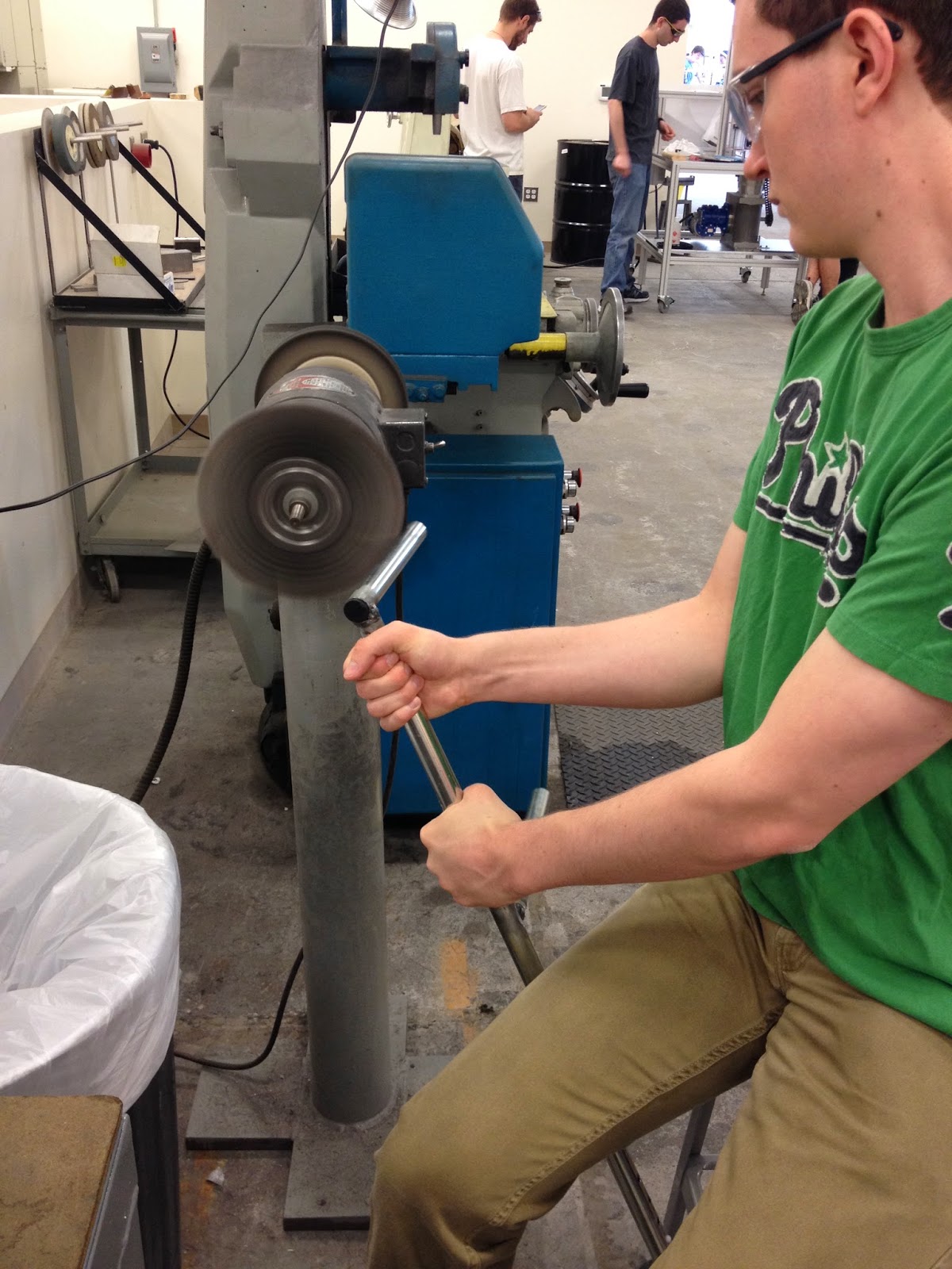
Due to the angled legs on the front of the walker, the initial measurements of the arm rests made it difficult to close into an easily stored, compacted device. A 5" long measurement of piping was made in the middle of each side and removed with a hacksaw initially, and then assisted with a bandsaw. These pieces of siding, as seen in Figure 1, would then be welded together to reconstruct the frame. Prior to welding these pieces, the exposed ends in the middle had to be sanded in order to remove the coating that covers the steel piping. One team member, in Figure 2, held the frame while the ends were being sanded, creating an easier spot for the welding to adhere and occur.

Next, the thinner sized piping was measured and fitted with two metal T-Plates, one on each end. While holding the T-Plate against the piping, two holes were measured and clamped onto the work bench. The holes were drilled and the T-Plate was riveted onto the piping. This piece would be attached to the walker shortly after the welding has been completed.
Another major detail that was addressed was the braking line system that would be attached to the front of the armrests. The handles with the attached brake line were disassembled previously and modified within the Machine Shop. First, the metal piping attached to the handle was measured and cut with bandsaw, to fit the thinner piping inside of. The idea was to flip the handle around so that it could be gripped from easily from resting position. After fitting the piping within the handle grips, two holes were drilled through the piping. These were then riveted to securely attach the new piping to the handle grips, as seen in Figure 3. The black wire hanging from the handle is the braking system that will be attached to the stopper at the bottom of the legs.

Due to the angled legs on the front of the walker, the initial measurements of the arm rests made it difficult to close into an easily stored, compacted device. A 5" long measurement of piping was made in the middle of each side and removed with a hacksaw initially, and then assisted with a bandsaw. These pieces of siding, as seen in Figure 1, would then be welded together to reconstruct the frame. Prior to welding these pieces, the exposed ends in the middle had to be sanded in order to remove the coating that covers the steel piping. One team member, in Figure 2, held the frame while the ends were being sanded, creating an easier spot for the welding to adhere and occur.
Figure 1: This image displays the cut and disassembled frame, waiting to be welded together.
Figure 2: This image shows one team member sanding the ends of the unpolished frame.
Another major detail that was addressed was the braking line system that would be attached to the front of the armrests. The handles with the attached brake line were disassembled previously and modified within the Machine Shop. First, the metal piping attached to the handle was measured and cut with bandsaw, to fit the thinner piping inside of. The idea was to flip the handle around so that it could be gripped from easily from resting position. After fitting the piping within the handle grips, two holes were drilled through the piping. These were then riveted to securely attach the new piping to the handle grips, as seen in Figure 3. The black wire hanging from the handle is the braking system that will be attached to the stopper at the bottom of the legs.
Figure 3: This picture displays one team member drilling two holes through the piping and handle.
After these adjustments were made, the disassembled frame was left with the Machine Shop to be welded together at the polished edges. The next step the team would like to accomplish is attaching the braking system to the walker, allowing the gripped handles to stop the walker from moving forward.
Wednesday, May 7, 2014
Week 6: (In-Lab) Further Construction and Planning
This week, our team took the constructed frame to the Drexel Machine Shop to address the issue of adjustable height on each of the legs. Initially when the wheels were fitted to each leg, there was only one hole to adjust the height of the walker. With careful measurement, the team decided it would be best if 4" of the legs were cut off, allowing there to be more options of height.
As seen in Figure 1, one of our teammates created a rivet in each leg to aid the movement of the handsaw as each leg was shortened. This would allow the decision of space between each hole to be made, prior to constructing in the Machine Shop.
After precise measurements, each hole was drilled 1" apart, allowing there to be four options of height for the proper use of the walker. The wheels that were previously disassembled from one of the out of lab activities were tested to make sure the pin could be easily adjusted between holes. In Figure 2, one teammate was marking out where the holes would be with a measuring tape, prior to drilling them.
 |
| Figure 1: This figure displays one of our teammates cutting the excess piping on the front and back side legs. |
After precise measurements, each hole was drilled 1" apart, allowing there to be four options of height for the proper use of the walker. The wheels that were previously disassembled from one of the out of lab activities were tested to make sure the pin could be easily adjusted between holes. In Figure 2, one teammate was marking out where the holes would be with a measuring tape, prior to drilling them.
 |
| Figure 2: One teammate marking holes for the pin of the wheels.
After each of the four holes were carefully drilled into the bottom of the legs, the two sets of wheels were fitted to see if the holes were big enough to hold the adjustable pin. As seen in Figure 3, the wheel pin is set to the tallest height option of the walker. The holes were drilled at a downward angle, allowing the pin to remain in place after being set to the proper height.

Figure 3: This picture displays the four rivets that were made for the adjustable pin.
Next, the set of wheels were modified using Gorilla Tape, around the piping of the wheel to prevent wobbling or slipping out of place. As shown in Figure 3, the wheel displayed is one of the back right wheels with the beginning stages of the attached braking system. This modification of using the black Gorilla Tape helped to thicken the thinner rod that slides into place of the legs. The stopper located on top of the wheel will be configured so that a braking line runs from the wheel to the brakes that will be attached to each arm rest. This stopper is attached to a spring that when pressed, drops the metal stopper onto the rubber coating of the wheel, allowing the walker to stop in motion. This system is the next step in the construction of the walker.
As seen in Figure 4 below, this is the initial structure of the walker that was completed with the help of the Machine Shop workspace. The multi direction wheels have been attached, allowing the front wheels to freely move in place. The back wheels, however, will be able to move as soon as the braking system is attached to the springs of the stopper.

Figure 4: This picture displays the beginning stages of construction of the walker.
The next plan for this design includes the finer details that will allow the walker to remain sturdy and withstand the designated tests to ensure results of proper posture. These tests, among others, will include the coefficient of friction and the range of movement the individual has when using the walker. The black back rest hanging freely on the back of the walker will be moved to a position that would be comfortable and supportive for any user. The other pieces of padding will also be added as soon as the walker withstands the team's expectations of providing proper posture and movement to an elderly individual.
|
Week 5: (In-Lab) Designing Phase
When initially designing the side frames of the walker, our team was going to use Aluminum pipes and rivet the pieces together. However, after going to the Drexel Machine Shop, we were advised it would be best to use Steel piping and weld the pieces together instead. Although we were unable to work on the physical construction of the frame, we were able to further design the minor details of the walker.
Next, we discussed the finer details of the walker, including the braking system and the wheels that would be attached to the legs. Essentially we decided we would use a brake line, as seen in Figure 1, from a disassembled bike that when pulled, would press the stopper against the wheel and allowing the walker to stop moving forward. The design of the wheel was originally supposed to be built with a thick plastic caster and spherical wheel, but it was decided to use wheels that were previously assembled. Then, the stopper was designed so that when it will be attached to braking line system, a metal stopper will press against the rubber wheel, with the use of a small spring.
After the realization of having to add the sensor for proper placement, our team decided it was best to not include this because it would be quite bulky when connected to the side arms. The trouble of compacting the walker was already a difficulty so adding this feature would have significantly impacted the minor goal of easy storage.
This In-Lab meeting helped the team to discuss finer details of the walker prior to construction. Although we were unable to begin building the basic frame, the brainstorming helped the team to see future goals that we would like to achieve in the few weeks ahead of us.
Next, we discussed the finer details of the walker, including the braking system and the wheels that would be attached to the legs. Essentially we decided we would use a brake line, as seen in Figure 1, from a disassembled bike that when pulled, would press the stopper against the wheel and allowing the walker to stop moving forward. The design of the wheel was originally supposed to be built with a thick plastic caster and spherical wheel, but it was decided to use wheels that were previously assembled. Then, the stopper was designed so that when it will be attached to braking line system, a metal stopper will press against the rubber wheel, with the use of a small spring.
 |
| Figure 1: This displays an example of the braking like we would like to disassemble from an old bike. <http://www.aliexpress.com/bike-brake-set_price.html> |
After the realization of having to add the sensor for proper placement, our team decided it was best to not include this because it would be quite bulky when connected to the side arms. The trouble of compacting the walker was already a difficulty so adding this feature would have significantly impacted the minor goal of easy storage.
This In-Lab meeting helped the team to discuss finer details of the walker prior to construction. Although we were unable to begin building the basic frame, the brainstorming helped the team to see future goals that we would like to achieve in the few weeks ahead of us.
Week 5: (Outside-Lab) Primary Construction
The majority of the construction of the walker was done during free time out of class this week. The first important task that needed to be done was to take the pipes to the machine shop in order to cut and sand them. This was done using a table saw and sanding belt by team members, as seen in Figure 1. The pipes were then welded by Mark, the machine shop advisor after the pipes were carefully laid out in the proper orientation. The frame was designed in three major pieces, two sides with 4 legs total, and a square back panel. These pieces were then held together with four door hinges as support. Door hinges were used because they provide the flexibility needed to allow the legs to fold inward, while also being strong enough to hold weight.
The second major task was to use a previously-owned "rollator" walker to salvage wheels and brake levers. Two stationary wheels, which would be used in the back legs of the walker, and two swiveling wheels, which would be used in the angled front legs of the walker to provide mobility. The team saw an opportunity to act on one of Dr. Seliktar's proposed ideas and use the existing brake to create a braking system that was always locked unless a lever was pulled. However, the existing brake was fashioned in a way that it only locked when the brake lever was applied. The initial braking system is shown in Figure 2 below.


 |
| Figure 1: Figure 1 displays the welding and construction of the walker's frame. |
Figure 2: This picture shows the initial brake system, which was unlocked unless the brake lever was applied.
While this setup did not fit the team's design plans, the parts were usable to create a new braking system. By sawing off the initial braking bar, and using an angled bracket to create a new braking bar on the same side as the brake wire, the team created a brake that was normally locked unless the brake lever was applied, which is shown in Figure 3 below.
Figure 3: This figure shows the redesigned braking system, which is locked unless the brake lever was applied.
After the frame construction and brake redesign, the walker's wheels were attached to thinner pipes, using rivets and welding, which can be inserted inside the legs to make adjustable height. Holes were drilled into the legs and thinner pipes, and a spring clip was inserted in the thin pipes to allow sliding.
Wednesday, April 30, 2014
Week 4: (Outside-Lab) Material Gathering
This week, we spent the majority of our time gathering materials to be used next lab period at the machine shop. At Home Depot, we spent approximately $40 on springs, zinc plates, and rivets to attach the aluminum pipes to make the frame of our walker. Below are pictures of the materials:
 |
| Figure 1: This image displays one of the zinc plates that will be used to joint the pieces together. |
 |
| Figure 2: This picture displays the Compression Springs that will be used for the walker. |
Additionally, during this week, the pipes were cut to appropriate lengths, so we can begin construction in the machine shop as soon as we arrive at class on Wednesday, 4/30. The pipes were cut at one of the group members' house with a hacksaw. We also found an old bicycle, which we need for the seat. We were unable to detach it so it will need to be sawed off sometime in the coming week.
Wednesday, April 23, 2014
Week 4: (In-Lab) Dimensions and Brakes
Today, our team discussed the physical dimensions of the walker to begin building the aluminum structure of the frame. As seen in Figure 1, a rough sketch was drawn with the determined measurements according to the estimated height of an elderly individual. The "x2" written on the right hand side of the picture indicates the dimensions applying to both sides of the walker.
After considering these dimensions, the initial idea of using a brake system with a gripping mechanism to stop the wheels from moving forward, another approach was decided. With the discussion contributed from Dr. Seliktar, the idea of using a bicycle seat and pressure obtained from sitting could potentially lock the wheels. In this sense, an individual who has difficulty applying pressure or gripping their hands tight could stop the walker easily.
Aside from the physical building process, a few tests were determined and discussed in terms of actually testing this design for an individual. Some of which will be sketched out to determine the force applied to make the walker stop as well as from tipping when going down an incline. These tests include:
 |
| Figure 1: This displays the determined dimensions of the walker. This will be applied twice, for both sides of the walker. |
Aside from the physical building process, a few tests were determined and discussed in terms of actually testing this design for an individual. Some of which will be sketched out to determine the force applied to make the walker stop as well as from tipping when going down an incline. These tests include:
- the angle of the back: range of the angle allowed and what would be typical (referenced to someone standing up)
- getting up from a seated position: applying a set amount of weight to show it won't topple over
- find coefficient of friction: make an argument of why it is sufficient, why it is stable
- maximum weight it can hold on the bicycle seat (force applied)
- maximum angle that would cause walker to tip over: measure in different positions
Week 3: (Outside-Lab) Meeting with Dr. Seliktar
After a brief meeting with Dr. Seliktar, we had a few more ideas to work with. Previously, we had been planning on bolting the aluminum pipes together to construct the frame. However, Dr. Seliktar suggested using triangular steel plates to hold different parts together would be simpler and more effective, as seen in Figure 1. He also mentioned that PVC could potentially be easier to work with because there are elbow pieces that can easily hold different pipes together. We would like to use aluminum because it is lightweight, durable, and more aesthetically pleasing. Although, PVC would be a suitable backup should aluminum be too difficult to work with.
Additionally, we talked with Dr. Seliktar in great length about seats and brakes. Dr. Seliktar seemed very fond of using a bicycle seat, as seen in Figure 2. This would enable the user to sit down and still move forward, but would not limit movement when the user walks normally. This is an intriguing idea, but would require the development of a more comfortable, cushioned bicycle seat that would be pleasant for older individuals to sit on for an extended period of time. Even so, it would be easier to install than a larger, folding seat.
When brakes were discussed, Dr. Seliktar suggested that the brakes be locked as a default. The brakes would be connected to the grips, and gripping the handle would release the breaks and allow the walker to move (almost like a reverse bicycle break). However, this would be concerning for people with arthritis; would they consistently be able to grip hard enough to unlock the breaks? Instead, there could be a spring powered break right over the wheel that would stop the wheel whenever the user sits down or applies pressure downwards. This is the likely plan of action, given that it is easier to build and simple to use.
Ultimately, Dr. Seliktar gave us valuable suggestions that have given us a clearer picture of the walker we hope to build. We plan to consult with him throughout the duration of the term about any questions we might have about walker mechanics.
 |
| Figure 1: This figure displays the idea of the triangular steel plates that would be attached to the aluminum pipes. |
 |
| Figure 2: This displays a sketch of the improved walker from the side, top and back views, with a bicycle seat attached instead of the original foldable seat proposed. |
Ultimately, Dr. Seliktar gave us valuable suggestions that have given us a clearer picture of the walker we hope to build. We plan to consult with him throughout the duration of the term about any questions we might have about walker mechanics.
Wednesday, April 16, 2014
Week 3: (In-Lab) Planning and Detailing
The primary focus this week consisted of the initial planning and detailing of the proposed walker design. First, the layout of the arm rests were sketched to decide how the sensors and physical arm rest would be placed on each side of the walker. The braking system was also considered, in terms of how the manual braking mechanism, located on each arm rest, would be connected to the spherical wheels on the front angled legs. One option, determined from the walker borrowed from Dr. Seliktar, included springs on the back two legs that stopped when pressure was applied from the arm rests, as seen in Figure 1.
 |
| Figure 1: This picture displays the spring brake attached to the wheel on the back legs of the walker.
The other option has been continuously brainstormed, consisting of a lever that is manually pressed, locking the system in place. A wire would essentially run through the piping, connecting to a rubber stopper inside of the spherical wheel casters on the front two legs. Though this idea seems complex, the idea is to safely lock the walker in place while providing comfort to the user when getting up from a seated position or while in motion. The ultimate goal of the braking and locking of the wheels consists of retaining the full range of mobility for the user.
|
The wheels attached to the walker were also a concern for the proposed idea. Multiple sketches were created to determine the best and most practical type of wheel to use and connect to the angled front legs. The idea of using a 3D printer to create the caster parts was considered, but the concern of the type of material created a drawback to this idea. Other multi direction wheels were researched in lieu of finding one with an attached brake that could easily be pressed with the user's foot, as seen in Figure 2.
The brake located on the side of the wheel could be an extra locking mechanism provided for the user. The only difficulty could be attaching this type of hardware to the proposed design. However, this type of wheel helped to further develop ideas of what the existing options are already.
 |
| Figure 2: This picture displays a "Richelieu" Hardware 60 mm Silver Plate and Brake Caster found after further research. <homedepot.com> |
Other walkers were observed to evaluate the best hinge mechanism for the arms and foldable seat. This included the walker that was at our disposal from Dr. Selikar that had the pressure-enforced spring brakes attached to the back legs, as seen in Figure 3.
 |
| Figure 3: This figure displays the walker that was provided to us during lab from Dr. Seliktar. |
With the use of this walker, the proper construction could be observed, which helped to raise other questions about the proposed design. This included:
- How the walker would be tested? (Non-human)
- What safety mechanism could be accounted for?
- How will the wheels lock in place from a seated position?
- How strong is the frame if enough weight is placed on it?
- How will the seat fold up and down?
Week 2: (Outside-Lab) Modeling Design
After researching the detrimental effects of Kyphosis on the spinal alignment, multiple virtual designs were created to establish a physical design of the improved walker. These ideas were illustrated through Creo Modeling, as well as Visual Analysis to determine the appropriate angle to be used for the front legs of the walker. This will essentially make the physical building process easier because the dimensions have already been established through these tools, as seen in Figure 1.
Although is only a basic design of the proposed walker, it includes features such as the user-friendly braking system located at the end of each arm rest, arm and back rest padding, as well as the foldable seat located on the back of the walker. The angled front legs will provide support as well aid in the braking system features. The angle of these legs were determined in Visual Analysis to find the amount of force that could safely be applied to each of the legs, as seen in Figure 2.
Using Visual Analysis, the ideal angle determined for the front legs was between 10-15 degrees. This was based off of the load distribution and space that the additional material of the angled legs would be accounting for.
 |
| Figure 1: This figure displays the basic Creo Model of the proposed walker design. |
 |
| Figure 2: This graph represents the load applied on the front legs with the degree of the angle used for these legs. |
Monday, April 14, 2014
Week 2: (In-Lab) Spinal Alignment Research
In today's lab, the focus remained on the physical condition of the walker user that progresses over prolonged improper use. Kyphosis is a serious condition that affects the elderly population, causing a decrease in lower back extension strength as well as a decline in everyday activity levels. This can create the "hunchback" effect that is common in the elderly community.
<http://www.sciencedirect.com/science/article/pii/S0003999308015682>
The walker's main design focus is to correct this improper posture, resulting from Hyper Kyphosis. This diagnosis consists of an extreme case of anterior curvature in the spine which can arise from muscle weakness or degenerative disc disease.
<http://www.ncbi.nlm.nih.gov/pmc/articles/PMC2907357/>
<http://www.sciencedirect.com/science/article/pii/S0003999308015682>
 |
| This figure displays the effects of Kyphosis, on the right, of the spinal alignment. <spinesurgery.com> |
<http://www.ncbi.nlm.nih.gov/pmc/articles/PMC2907357/>
Wednesday, April 9, 2014
Week 1: (Outside-Lab) Preliminary Research
This week, the main objective was to research and contact various companies about the list of materials comprised for building the modified walker. This list included:
- aluminum- metal framing and structure
- foam padding- back rest, arm rests
- wheels- spherical wheels
- joints- locking hinge
- various mechanical hardware
After further research of the different types of wheels that could be used to move in all directions, a caster made of aluminum or thick plastic will be molded around the wheel.
The piece on top will be used as part of a braking system to stop the walker, as fail-safe. On the arm rests, a button will be pressed allowing a rubber stopper to rest on the wheel safely.
 |
| This figure displays the potential wheel design that is intended to be used on the front and back legs of the walker. |
Various locking hinges were addressed to use for the swinging mechanism that would function in the aspect of getting into the walker as well as how easily it folds/stores.
 |
| This figure displays a locking hinge mechanism that could be used for the sides of the walker. |
The flexibility of this hinge will allow one side to completely open horizontally, allowing the user to enter the walker with ease. While the pictured joint locks in multiple places, the team's joint will only need to lock in one place.
The majority of the outside group work involved researching materials, necessary hardware and planning out the design process to successfully create an improved prototype of the walker.
Friday, April 4, 2014
Week 1: (In-Lab) Brainstorming
Initially, our group brainstormed several design constraints to be considered when creating the initial design of the walker. These consisted of:
When considering these constraints, the design allows the user to remain in an upright position while improving the posture conditions associated with regular walker designs. In terms of being lightweight, foldable and compact, the sides of the walker will be able to fold inwards to be easily stored. This swinging mechanism also functions as a response to the concern of getting in the walker from a seated position. The use of aluminum or stronger metal will allow the walker to support the full weight of the user. A comfortable back padding will provide support and comfort against the user's back, while connecting to the foldable seat attached underneath the padding. At the bottom of the angled legs in the front and the vertical legs in the back, an Omni Wheel will be used that can move in all directions. On each arm of the walker, a sensor device will detect for proper placement of the user's limbs, providing a sound to indicate this placement. The handles attached to the ends of each arm will provide support as well as a brake button that will be easily graspable and connected to a rubber stopper above the angled legs' wheels. This will allow the walker to stop moving safely.
- lightweight, foldable and compact
- springs for impact
- mobile in all directions
- sensors for proper detection of use (sound for approval)
- affordable
- aluminum or other stronger metals
- possible seatbelt, break-away restraint
- back rest long enough for entire back's length
.jpeg) |
| Top, Back and Side View Sketches of Proposed Walker Design |
Subscribe to:
Posts (Atom)